In my previous post I asserted that Tesla vehicles are at their core computers on wheels. The electronic and mechanical systems are designed in a modular fashion and communicate with each other over multiple CANBUS networks with high speed two way information flows.
If you want to access vehicle data and more specifically driving information, then you need to tap into the appropriate bus and filter the messages for the ones you are interested in.
What is a CANBUS network?
A CANBUS network is a two wire network which requires a minimum of two nodes although there can be (many) more than two. There is no concept of master or slave; each node on the network is a peer of each other node.
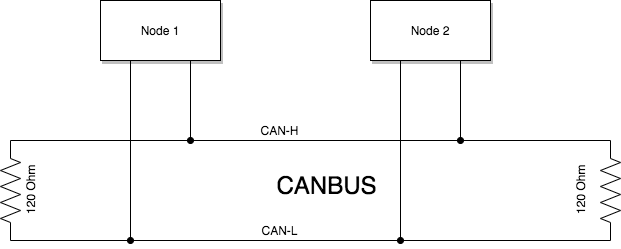
The network works using differential voltage signalling on two wires; normally designated CAN-H and CAN-L. The network also requires a termination resistor (typically 120 ohm) at each end to avoid signal reflection.
According to the CANBUS specification, nodes can transmit and receive messages at up to 1Mbps (bits per second). Tesla’s CANBUS networks typically operates at 500kbps with around 1-2k messages per second transmitted on the bus.
The simplicity of implementing a CANBUS network coupled with high speed data transmission (based on the short wire lengths in a car) is what makes CANBUS an adopted standard for auto manufacturers. It’s basically reliable, simple and cheap.
Although it’s not critical to understand how the signalling on the two CAN wires works. it is useful to know that the data is ultimately transmitted as binary data represented by a seequence of 0’s and 1’s and that nodes cooperate in a way (using message precedence) in order to avoid message collisions on the bus - this prevents one node from transmitting at the same time as another.
DBC Files
There is a standard (file format) for documenting the messages on a CANBUS network - these files are called DBC files. The DBC files list the different message types (records), and the data (fields) within each record type.
This is an extract from a Model 3 DBC file describing message ID 614 (0x266 in hex) RearInverterPower which represents the power limits and power being used while driving.
BO_ 614 ID266RearInverterPower: 8 VehicleBus
 SG_ RearHeatPowerMax266 : 24|8@1+ (0.08,0) [0|20] "kW"  Receiver
 SG_ RearPowerLimit266 : 48|9@1+ (1,0) [0|400] "kW"  Receiver
 SG_ RearHeatPower266 : 32|8@1+ (0.08,0) [0|20] "kW"  Receiver
 SG_ RearHeatPowerOptimal266 : 16|8@1+ (0.08,0) [0|20] "kW"  Receiver
 SG_ RearExcessHeatCmd : 40|8@1+ (0.08,0) [0|20] "kW"  Receiver
 SG_ RearPower266 : 0|11@1- (0.5,0) [-500|500] "kW"  Receiver
This CAN message is transmitted at 10Hz (ten times per second). Other message types will be transmitted more or less frequently depending on the importance of the message. Some messages are transmitted just once after the vehicle starts up, so if that particular message is important to you, you need to ensure that you capture it when it is sent or you will miss it.
Decoding a CAN message
You can use the DBC message specification to understand how to interpret the bits of each message field within the CAN message data payload.
All numeric values are presented as whole numbers with a divisor or multiplier applied afterwards to produce a floating point number (if necessary). The numeric values don’t always follow standard 8 bit byte boundaries and this can make determining the actual numeric value a little tricky.
There is also another factor that comes into play too. Numeric values transmitted in CAN messages are represented as (variable bit length) integers in Big Endian format. However most processors use Little Endian integer representation so you will probably need to convert between these integer representations within your code in order to arrive at the correct numeric value.
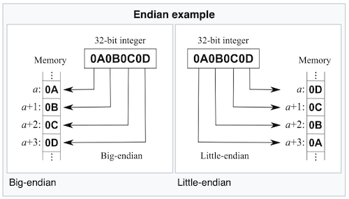 See https://en.wikipedia.org/wiki/Endianness for a full explanation on this topic
Let’s take the RearPower DBC field specification as an example and break it down into its constituent parts:
SG_ RearPower266 : 0|11@1- (0.5,0) [-500|500] "kW" Receiver
RearPower266: this field represents Rear Power with a message ID of 0x266 (hex)0: value starts at bit 011@1: value is 11 bits long with a sign bit(0.5,0): value given is twice the actual value (so needs to be divided by 2)(-500|500): value varies between +/- 500 (KW)
Interpreting this value correctly as a floating point number can be achieved in the C programming language as follows:
  // SG_ RearPower266 : 0|11@1- (0.5,0) [-500|500] "kW"  Receiver

  // convert from big endian to little endian
  // by moving 3 bits 8-10 in front of 8 bits 0-7
  uint16_t ud = ((bytes[1] & 0x7) << 8) | bytes[0];

  // convert from an unsigned integer to a signed one
  int16_t sd = ((ud & 0x400) == 0x400) ? ud - 0x7FE - 0x02 : ud;

  // convert to a floating point number and divide by two
  float power = (float)sd / 2.0f;
In order to access CAN message’s numeric values you ideally want to be using a programming language that supports working at the bit level.
Tesla’s CANBUS networks
All Tesla cars including the Model 3 and Model Y have multiple CANBUS networks or channels. Of the channels available in the vehicle, two are most relevent for displaying driving information; these are the VehicleBus and the ChassisBus networks.
In order to access the correct CAN bus, you need to first identify which bus to use based on the messages available on it, and then determine which wires represent the CAN-H and CAN-L pair. You will also need a ground and power in order to drive whatever unit you connect.
There are a few different locations to access the VehicleBus and ChassisBus on a Model 3.
- The connector at the rear of the console between the two front seats
- A connector under the front seat
- A connector behind the dashboard near the HV module
These are not the only locations because in theory you can tap into the wiring loom wherever you can gain access. I have been vague about these locations on purpose because I do not want to be responsible for you damaging or voiding the warranty of your vehicle.
You’re probably wondering how to find out which pins of the connectors represent the CAN-H and CAN-L signals for each bus. The answer is that it varies between connector and is usually determined using a multimeter and CANBUS analyser through a process of trial and error. Thankfully much of the information you need is available from the Tesla forums and this is the best source of this information.
If you do connect to your vehicle bus, make sure you use a fuse for the power feed to your device, and consider using CANBUS adapters that feature opto-isolators in order to prevent voltage surges from the vehicle damaging your connected device and vice-versa. Never transmit messages onto any bus that you connect to as this may have severe and unintended bad consequences.
Please understand that if you decide to do connect to your vehicle’s wiring, you do so ENTIRELY AT YOUR OWN RISK AND THAT I WILL NOT ACCEPT RESPONSIBILITY FOR ANY DAMAGE CAUSED.
Development without a Tesla vehicle
Now that I have cautioned you about connecting to the vehicle’s CAN buses, it’s important to note that you can still carry out development work without requiring a vehicle at all. This can be achieved by using a CAN recording file and some simulator software instead.
There are many Vector (*.asc) format logs taken from Model 3’s and Model Y’s on the internet that you can work with. These files are captured recordings of driving sessions in a vehicle with all the messages seen on the bus and the timestamps for each message. This allows you to replay a driving session using your own CANBUS network.
This is a sample Vector format (*.asc file) recording taken from a Model 3
date Wed Oct 2 12:10:47 pm 2019
base hex timestamps absolute
Begin Triggerblock Wed Oct 2 12:10:47 pm 2019

 1.372245 1  3A2        Rx D 8  AB  04  00  00  00  00  00  00
 2.372990 1  3E8        Rx D 8  02  00  00  00  00  00  00  00
 3.373238 1  3DA        Rx D 8  00  00  00  00  00  00  00  00
 4.373472 1  7AA        Rx D 8  72  08  36  FA  60  09  21  00
 5.373708 1  243        Rx D 8  FF  7F  FF  7F  62  12  20  48
 6.373939 1  287        Rx D 8  44  44  44  45  09  03  00  00
 7.374181 1  78A        Rx D 8  01  00  07  00  00  00  AB  04
 8.374445 1  2C4        Rx D 8  0D  25  4A  94  00  00  00  00
 9.374679 1  263        Rx D 8  01  84  7A  BC  E8  7E  FA  02
 10.374931 1  204        Rx D 8  01  00  00  00  00  00  00  00
 11.375165 1  224        Rx D 8  44  08  A9  00  13  01  10  08
 12.375373 1  264        Rx D 6  70  00  00  00  E0  01
 ...
And this is a breakdown of the fields/columns:
- Timestamp
- CANBUS channel (captured on)
- CAN Message ID
- Direction
- Data length
- Data fields 1…n
Creating your own CANBUS network
If you want to replay CAN messages then you will need to create your own CANBUS network. The simplest method of doing this is to purchase two USB-CANBUS adapters and connect them both to a single computer, or use two computers (as shown in the image below). The adapters shown here are from Inno-maker.
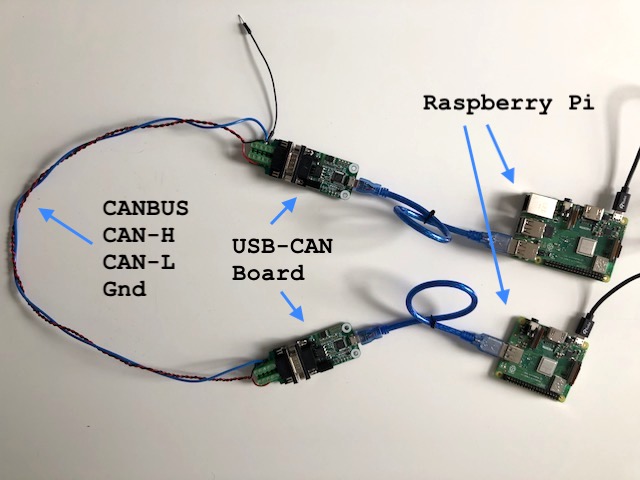
In order to create a network, you need to connect three wires between the two USB adapters:
- GND (Ground)
- CAN-H (CAN high signal line)
- CAN-L (CAN low signal line)
It is entirely possibly to avoid needing a second USB adapter and replace it by a 120k Ohm resistor instead. However the value of having two commputers connected is that you can use one to transmit messages onto the bus, and use the second to confirm that they are being transmitted correctly.
If you want to connect both adapters to a single computer, then you will need to ensure that it is powerful enough to be able to transmit and receive CANBUS data (by servicing the interrupts quickly enough) especially at high transmission speeds; like those found on the Tesla vehicle network.
Replaying ASC log file recordings
In order to be able to replay the ASC recordings on my CANBUS network, I created a unix command line simulator application which allowed me to select the recording file to simulate, and control different aspects of the playback (like looping, message playback speed etc).
I have released this as an open source project at https://github.com/codingoverdrive/vehicle-canbus-simulator.
The project documentation explains how to configure your USB-CANBUS adapter using the can-utils package to set the CANBUS speed correctly and specifically at 500k bits per second if you want to replicate the Tesla bus speeds.
Summary
Hopefully this post has demystified some of the inner workings of Tesla’s cars, and that you will be able to use this information here for your own Tesla project.
In the next instalments, I will take a look at a custom device I created that is able to listen to CAN messages and relay them to a subscriber, and describe how I want about creating a display to visualise the vehicle data in real-time.
References and Resources
- For more information on the CANBUS protocol and how it works visit CANBUS information on Wikipedia
- My open source project will allow you to simulate a CANBUS network using a configuration similar to the one above
- Josh Wardell has published a DBC file for the Model 3 on Github