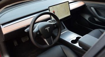
 When Tesla released the Model 3, they removed the instrument cluster that is traditionally behind the steering wheel. The information normally presented there is instead provided on the large landscape display in the center of the dashboard
I believe that they did this for two main reasons; cost cutting and also because they expected that these cars would be capable of self driving at some point in the (near?) future rendering a driver and the need for extra driver information redundant.
In the Model S and X, the instrument clusters still exist and provide speed, gear, power consumption, battery range, temperature and autopilot information. There are also two ancilliary areas on the left and right of the cluster display which can be customised to provide other information like navigation, power usage, entertainment/music information, trip data, tyre pressure data among others.
Although drivers new to the Model 3 initially miss the instrument cluster they also state that it doesn’t take long to get used to shifting your eyes to the center of the car to access the same information on the large central display.
I don’t really like the idea of having to take my eyes off the road in order to see driving information (like your speed) which is only on the central display. So my preference and a desire to understand more how Tesla cars work is what spurred this project on. Although I don’t own or drive a Model 3 or Model Y, it wasn’t too hard to get around that little problem and still develop a prototype which works with either of these two newer Tesla models.
These were quite a few things that I needed to figure out in order to arrive at a working prototype including the following:
1. What vehicle data is available and how to access it
Tesla vehicles are at their core computers on wheels. The electronic and mechanical systems are designed in a modular fashion and communicate over multiple CANBUS networks with high speed two way information flows.
In order to create a driving display, you need to identify which of the CAN buses contain the information you are after, and then figure out how to physically access the network. This is similar to creating a “phone tap” which allows you to listen in on the messages flying across the bus.
Not only do you have to identify the correct bus and gain access but you also need to identify which of the messages contain the information that you want and how to decode it. This is not a trivial process but I was greatly aided by information shared within the Tesla owners’ community that has and is being constantly updated through reverse engineering techniques. Tesla does not share their CANBUS information publicly.
2. What hardware and software to use to display driving information
Tapping into a CANBUS network requires some engineering and electronics knowledge that is relatively easily acquired. CANBUS is a standard 2 wire protocol so the wire tap involves adding a passive listener on the bus in a way that doesn’t compromise the bus. The listener is a hardware device that you need to create which can capture messages and relay them to the disply unit.
The display unit could be any kind of device; a mobile phone, an embedded device or a custom solution. I chose to create a custom hardware solution based on some relatively cheap and readily available hardware. With that selection made, I then researched what software frameworks and libraries were available that would enable me to create real-time data visualisations.
The hardware device specification and the need for real-time visualisations created some constraints on the programming language used and I spent a some time evaluating different software options before settling on one that would give me the performance needed while also allowing me access to a powerful graphics library.
3. Sharing data between the vehicle and the display unit
It is a good architectural principle to decouple and isolate disparate systems as much as possible. This is the approach that I also took for this project where the hardware CANBUS “tap” and the display unit were created as two separate hardware devices; each with their own software stacks.
This approach allowed me to break the project into two separate problem spaces and to solve them independently. This worked out very well as the expertise required is each area is quite different and it allowed me to ramp up my knowledge in an incremental and more manageable way.
Having designed for two independent subsystems I had to figure out how to connect the two systems; both in hardware and software terms. Two options presented themselves; a physical connection involving wires between the devices or a virtual connection using a wireless protocol. I chose to use a wireless protocol as this gave me the most flexibility and allowed me to build and easily test the two devices both in isolation and later together.
4. Creating a working prototype display without access to a vehicle
No one in their right mind would consider starting a project like this by getting into a Tesla with a laptop and a hardware CANBUS bridge and writing software as the car is being driven around in order to get access to the CANBUS messages.
So instead I created my own CANBUS network on my workbench. This was an invaluable exercise as it allowed me to really understand how a CANBUS network works, and how to correctly tap into it in order to access the messages being transmitted on the bus.
With a physical network available, I injected CANBUS messages onto the bus that I could “listen” for using my wire tap. I used different CANBUS messages sources starting with some basic ones before finally using recordings of CANBUS messages from driving sessions shared by Model 3 owners.
In order to replay the messages on my own CANBUS network, I created a software package that would read a CANBUS recording and then replay the original CANBUS messages at the correct speed and in the correct format. I have shared this package of the project as open source one because it might benefit anyone else wantng or needing to create the same kind of test environment.
With a working CANBUS network simulating the same bus in a Tesla Model 3, I was able to develop a custom wire tap or listening device using embedded hardware and my own software running on it. This listens to all the messages on the bus and then relays them to any upstream subscriber such as my disply unit.
This is how I was able to create a Model 3 environment on my workbench without needing to write code in a vehicle being driven around by someone else. This approach and technique is pretty common in systems development and I haven’t really reinvented anything that isn’t already a pretty standard way of going about this sort of thing.
Summary
At the outset of the project, I had no idea whether I would able to create the display device I envisaged in my mind. Each aspect of the project highlighted the huge gaps in my knowledge that needed to be filled and this is where a lot of time was spent; understanding the problem space, learning how things work and which technical options would be best to use as a solution.
This is probably one of the most technically demanding projects I have undertaken recently combining both hardware and sofware challenges and solutions. Looking back now, I am amazed at how steep the learning curve was but how the solution was incrementally arrived at by breaking each challenge down into the smallest step possible and solving that before moving onto the next problem.
In the next instalment I will dive more deeply into Tesla’s CANBUS network and how to “tap” into it and access vehicle data in real-time.